Technical Desktops
 | 98x5 Computers Selection: |
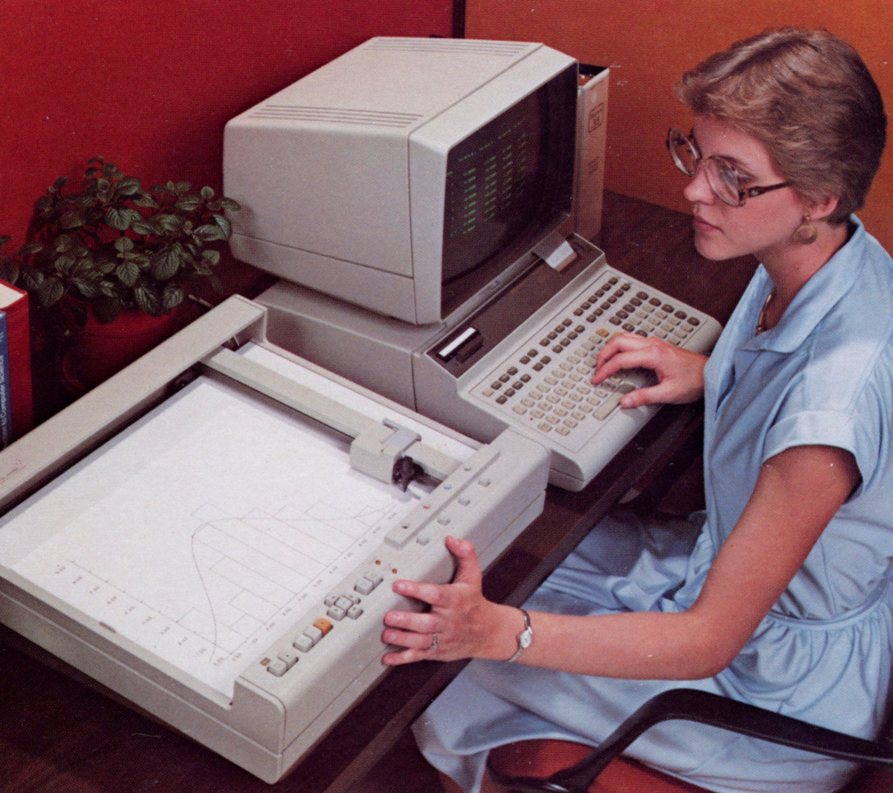
| Name: 9835 | |
| Product Number: 9835 | |
| Introduced: 1978 | |
| Division: Desktop Computer Division | |
| Ad: Click to see | |
| Original Price: $9900 | |
| Catalog Reference: 1979, page 621 | |
| Donated by: The Macservice Group, Victoria. |
Description:
The 9835A was a lower-cost version of the 9845A. It used the same housing as the 9825, with three expansion slots, single tape drive and optional 16-character internal thermal printer. It had the same twelve-inch screen as the 9845, but without graphics capability. The 9835A was program-compatible with the 9845A. The 9835B cost $1200 less than the 9835A and included a single-line LED display instead of the CRT display. ROMs for the 9835 were unique to that machine, and not compatible with the 9845 or 9825.
The 9835A and 9835B were obsoleted on March 1 of 1983.
Collector's Notes:
To use your 9835 with a 9895A 8-inch floppy drive, you will need the "B" version of the mass storage ROM (98331B). The "A" version of the ROM works with the 9885 8-inch floppy drive (and other drives). To connect to the 9895A, you will also need the "B" version of the HP-IB interface (98034B). The 98034A will happily connect to most HP-IB peripherals, but not to the 9895A.
Fixing Monitor "Screen Mold":
It is unusual to find a 264X terminal, 262X terminal, 9845 monitor or 9835A monitor that doesn’t have what appears to be mold growing just under the surface of the screen. These inclusions start around the edges of the screen as small gray dots, then multiply and grow to become large gray dots. Eventually, the entire screen can become obscured. In addition, a white material begins to seep out of the monitor enclosure. This material looks like capacitor leakage or battery corrosion.
This situation is not caused by mold, leakage or corrosion. Rather, these CRTs all have a glass plate glued to the front of the screen. The glass plate is 3mm thick and the layer of transparent glue is 4mm thick. The “screen mold” appears as the layer of glue starts to break down. The spots appear on both the inside and outside surfaces of the layer of glue. The breakdown of the glue and existence of the spots does not affect the functionality of the screen. A screen with hundreds (or thousands) of spots will work just as well as a screen with no spots. However, the more spots a screen has, the more difficult it is to read.
In some cases, a screen will become very difficult to read because of the spots caused by the glue breakdown. It is possible to fix this problem by removing the glass plate affixed to the CRT and cleaning off the glue residue. Be sure to click on “More Images” below to view photos of the various stages of this process.
The first step is to remove the CRT from the monitor/terminal housing. The CRT only has to be removed enough to gain ready access to all sides of the screen. Remove the black tape that runs around the perimeter of the screen and covers the edge of the glass plate and the glue layer. Once the tape is removed, it will take around two hours to dig out the glue in the 4mm space between the CRT and the glass cover. You can reduce this time to about an hour if you are willing to break the glass cover. The only reason you would want to keep the glass cover is to reinstall it after you have removed the glue residue (and keep your screen as close to original as possible). In most cases, you will want to use the screen without the glass cover or to replace it with fabric (no glare) or a thin Perspex sheet (like the monitor on the 9836). In either case, you would attach your new screen cover to the monitor housing and not glue it to the CRT glass.
Use a small, flathead screwdriver (3mm blade) to dig out the glue layer. You remove the glue layer by cutting out small sections of the glue at a time. Make a series of insertions into the glue layer across the top of one edge of the screen. These insertions should be about 2 cm deep and made at an angle of 45 degrees off vertical. The insertions should be spaced 1 cm apart. Then, make perpendicular insertions across the same edge of the glue layer. As you make these insertions, you will be able to pry and lift small blocks of the glue from under the glass screen. The process takes awhile. Once you have removed the 2 cm of glue from one edge of the screen, use the same procedure on the other three edges.
After you have dug out the glue around all four edges of the screen, you can break off some of the glass. To do this, insert a larger flathead screwdriver (6mm to 8mm) between the CRT and the glass cover. Then, slowly twist the screwdriver to create pressure between the CRT and the glass cover. Part of the glass will break and can be easily removed. You do not have to worry about scratching your CRT face because the steel screwdriver you use is softer than the glass face that it is prying against. But, be careful if you use a sharp knife to cut away exposed glue residue. You can scratch the CRT glass if you press down too hard using a sharp knife to cut away the glue. We did this the first time we removed a glass screen cover (as seen in the photos). These scratches can be buffed out. Using the twisting screwdriver technique, break off the glass around the circumference of the screen. You should be able to remove a little over half of the glass in this manner. Once this first round of glass-breaking is complete, you repeat the process of inserting the small screw driver and prying out the glue around the edge of the remaining glass. When you have 2 or 3 centimeters of glue removed around the remaining glass, then use the large screwdriver to do another round of glass breaking. Eventually, you will remove all the glass and glue.
If you wish to keep your glass cover intact, it will take longer to remove the glue and glass. We managed to do it by performing the above procedure, but very carefully. It becomes tricky as you get deeper in to the glue. You still use the large screwdriver to pry the glass, but be gentle and careful. Your objective is to loosen the surface tension between the glue and the glass/CRT. As you do this you will see space develop between the glue and other surfaces. But, if you twist the screwdriver too hard, you will break the glass cover (but there is never really a risk of breaking the CRT glass itself). We also used a hot wire to help cut through the glue. Our hot wire only penetrated 5mm or 6mm into the glue. Our hot wire was powered by a 12 VAC 800mA transformer. More grunt would probably have been useful. It may also be possible to speed the degradation of the glue by applying a solvent to the glue after each round of glue digging. We didn’t get around to trying this. We also have not attempted to glue a removed glass cover back onto the CRT screen. We would certainly be interested in hearing from anyone who has done this successfully.
Once you have removed the glass cover and glue from your CRT, you will find that the screen image you get is even better than that from a monitor with no “screen mold”. This makes sense because you have basically removed two filters from your light source.
Other:
If you have just obtained an old 9835, we recommend the following procedure for start-up/troubleshooting:
- When you first power up, apply voltage slowly using a Variac to allow your electrolytic capacitors to recondition themselves if they haven't been used for awhile. Two four hour ramp up sessions should do the job. Be sure to remove any front-pluggable ROMs before continuing.
- If your unit won't turn on at all, then you probably have a problem with the power supply PCB (assuming you have already confirmed that your fuses are okay). This can be repaired using the schematic in the service manual. If your fan turns on, but you don't have output to the display, check the output voltages for the power supply as instructed in the service manual.
- Your computer should emit a beep as soon as you turn it on. If it doesn't, you won't get output to the display. The problem could be with the processor board, operating system ROM, or with a memory board. The only easy assembly to test is the memory board. Most 9835s have between two and four memory boards. The unit will work happily with just one memory board. The machine will not beep if the block 0 board isn't working. To test memory, remove all memory boards except the block 0 board. Power the unit up again and see what happens. If it still doesn't work, remove the block 0 board and replace it with another memory board. Be sure to change the address of the new board to be block 0; the four-dip switch is set to address 0 and the two-dip switch is set to "special" (see service manual).
- When you power up your 9835, you may get output to the monitor, but the output is in the form of strange characters and doesn't respond to keyboard input. This problem could be due faulty CPU board, system ROM or memory board. Test memory as per above. You can confirm that the monitor itself is working by pressing and holding the "D" test button at the rear of the monitor. If your monitor is working, it will display a full screen of all the characters (including inverse) that the monitor can display.
- If your PSU voltages are good, and you get the beep on power up, but you still don't get output to the display, turn the computer off and remove the display. Turn the computer on again. After the initial beep, the machine will go quiet for about five seconds. After that five second period, it should start beeping rapidly to indicate that the display is not attached. If the rapid beeping never happens, then you probably have a problem with the system ROM drawer or the CPU board.
The monitor for the 9835A is not as robust as the similar monitor for the 9845. Only two of the five monitors we have at the museum (as of 2014) are operational. Only two of the five base units are operational as well. Memory boards and system boards are common failures. Of the six system ROM drawers in our possession, two have failed. We were able to fix one of them by swapping ROMs from the other bad system ROM drawer.
The single 9835B that we have is also functional.
Paul Berger of Nova Scotia has read the contents of all of the 9835 ROMs and also created a 64K RAM board for the computer. Click here to download the details.
Paul has also created a 9835A RAM expansion card allowing a 9835A to have over 512Kb of memory!. Click here to download the details.
Ansgar Kuekes has created an amazing utility for allowing a modern PC to emulate disc drives for the 9835. To run "hpdrive", you only need a GPIB card for your PC and a 98034 HP-IB interface: HPDrive. Using Ansgar's "HPDir" utility, you can use your PC to perform disc operations on the old software (copy discs, transfer files, etc): HPDir
| Back | More Images | Product Documentation | Category Accessories |
^ TOP©2004 - 2026 BGImages Australia - All Rights Reserved.
The HP Computer Museum and BGImages Australia are not affiliated with HP Inc. or with Hewlett Packard Enterprise. Hewlett Packard and the HP logo are trademarks of HP Inc and Hewlett Packard Enterprise. This website is intended solely for research and education purposes.