Peripheral Products
 | Pen Plotters Selection: |
| Name: 7580 | |
| Product Number: 7580 | |
| Introduced: 1981 | |
| Division: San Diego | |
| Original Price: $15950 | |
| Catalog Reference: 1982, P. 690 |
Description:
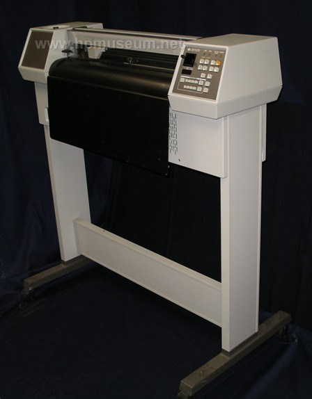
The 7580A (code named "Bertha") was the world's first "grit wheel" pen plotter. This machine combined high speed and high line quality in a small package at a price less than half that of comparable products on the market at the time. Small grit-covered wheels move the paper along the X-axis of the 7580A, replacing the heavy, bulky components used in other plotters with a low-mass, low-inertia drive mechanism.
This design permitted the use of lighter parts and less expensive drive motors while retaining high reliability and plot quality. The 7580A also incorporated design innovations in microprocessor design, firmware, language and pen handling. It represented HP's entry into the large-format plotter market, causing great distress to industry veterans Calcomp and Versatec. Within six years, HP commanded a market share of almost 50%. Click here to view a 9 second video of the 7580 in action (1.5 MB).
The 7580B replaced the 7580A in February of 1983. The primary improvement offered by the B version was a dual interface (HP-IB and RS-232) as standard.
The 7580B was obsoleted in September of 1987.
Opportunity Discovery Assignment - One day in 1977 Tom Tremble and I both found ourselves doing little orbits in the hallway outside of the closed door of the HP San Diego conference room where division executives were holding their monthly staff meeting. At the appointed time, we were ushered in where we received an unexpected assignment, "We want you two to figure out what it will take to get HP into the large format drafting plotter business. Work at this about half time, and report in with us every other month or so and let us know what you are learning. Spend whatever you need on travel."
In less than 15 minutes we were back out in the hallway looking at each other, puzzled. We hardly knew one another. Tom was a product marketing manager and I was a project manager in the R&D lab. Over rest of that year and part of the next though, we became good friends and learned much together.
The Large Plotter Market - In the late 1970s two firms, Calcomp and XYnetics dominated the US market, while a French company, Benson, held sway in Europe. Calcomp offered innovative designs that held the record for acceleration and plotting speed. Their most recent offering, for instance, utilized a Mylar belt stretched over sprocketed rollers at top and bottom. The drawing medium was taped to this belt which then moved the drawing surface back and forth underneath a pen carriage moving right to left above the top roller. This machine sold for about $30,000. XYnetics machines were the gold standard for accuracy and were built onto a polished granite slab weighing about 1000 lbs. A waffled steel plate embedded under a smooth plastic layer was bonded to the top of the slab, and the drawing medium was taped to the smooth upper surface. An X-Y motor carrying four pens was moved around by magnetic forces and was suspended above the drawing medium on an air bearing. The cost for such a machine was around $50,000 or more. Once this plotter was in place and temperature stabilized (a process that could take a couple of weeks), it delivered unparalleled accuracy.
These machines were used to create drawings of all kinds, mechanical, electronic schematics, architectural, and more. Really accurate plots were sometimes used as templates in fabricating finished goods such as clothing or large sheet metal parts.
Market Insights Discovered - In discussions with an architect in Bath, England we learned that a liquid ink pen failure could cost $1000. He had designed a strip shopping mall that was being replicated again and again in Saudi Arabia. Local regulations demanded that each drawing be plotted on Mylar in India ink. His days were spent cleaning liquid ink pens and keeping his half-dozen large format plotters constantly running. "When you break it down," he said, "Each of these drawings is worth about $1000. When a pen clogs or dries up in mid-drawing, I have to throw the whole thing away and start over."
Almost as an after-thought, he added, "Oh, by the way, if you plan to sell me plotters, you had also better be able to supply the pens, inks and drawing media as well. My nearest drafting supply store is in London. It costs me a whole day to get there, buy what I need and get back here." Back in the US we visited an integrated circuit design company in the Boston area. There we saw several big XYnetics plotters in action turning out plots that depicted individual layers of a chip design. When I asked, "Can you show us how these drawings are used?" we were ushered into a huge room filled with large light tables about two feet high. Each had several large and carefully aligned drawings taped to its top surface. Engineers in white lab coats and booties were crawling around on top of each light table sighting down through the drawings to ensure that each layer was correct, and well aligned with layers above and below. I know that computer software does this job now but, back then, that’s how it was done.
Our host pointed out, "You can see now why we need such accurate plots. Each individual drawing needs to line up perfectly with the other layers." I observed that they weren’t really depending on accuracy, they were using repeatability. Each long line could be short by perhaps a half inch and, as long as all plots were in error by the same amounts, the drawings would still line up, and their process would work just as well. He grudgingly admitted that this might be true. As long as all plots for a given chip were made on the same machine, high repeatability with lower accuracy would work just as well and could be accomplished with a much less expensive plotter.
Finally, during a visit to a construction site in the desert about 20 miles out of Phoenix, Arizona, a civil engineer told me, "If you want to sell me a plotter, it needs to fit in this little temporary office here. Also know that I’ll either buy your plotter that year or a new pickup truck. So your plotter had better be more valuable to me than that new pickup truck."
Discovering the Essentials of "Drafting Quality" - Knowing that the unit manufacturing cost (UMC) of our eventual product would be driven by various product specifications, e.g. accuracy, repeatability, pen acceleration, and pen handling, we launched a technical investigation into this idea of "drafting quality" and the plotter performance constraints that would be essential in achieving it. Hundreds of archived drawings created by humans were studied in minute detail to develop a performance baseline.
They proved to be a tough act to follow. Lines were always impeccably straight, and the smallest details were nearly perfect. India ink drawing pens, for instance, leave a little, round blob at the end of a line where their motion has come to rest. The diameter of this blob is about 1.5 times the width of the line. Many draftspersons will follow up by trimming these blobs even with the line edges with an X-Acto knife. In our investigation we learned that this blob takes time to form so, if the pen is lifted or the next line segment leaves from that point within a few milliseconds, it doesn’t occur at all.
Knowing that designing our product to perform as well as a person would increase its UMC prohibitively, we decided to explore the human observer’s ability to visually detect flaws in a finished drawing. The test bed for our work was a breadboard consisting of a large 36-inch wide flatbed plotter along with the external computers, motor drive electronics and power supplies that were required. We learned that deviations from a straight line that occur repetitively over short distances, an inch or less, will be noticeable if they are more than about 0.001 inches in magnitude. On the other hand, a long line of 36 inches can smoothly deviate by as much as 1/2 inch in the middle, and still look straight to the unaided eye. This study provided essential design guidelines for our product.
Bill Hewlett Starts a Side Project - During the time we were working with this large flatbed, HP’s San Diego division had its annual review with the company’s executives. These reviews always included a tour of key projects in the R&D lab. When Bill Hewlett saw our big flatbed, with its huge 1 hp servo motors and massive external power supplies he wondered why all that hardware was required to move around a teensy 1/2 oz pen. This was a good question and Bill later discussed it with his friend Larry LaBarre up in HP Labs (HPL) up in Palo Alto. "Why don’t you invent a better way to move a pen around on paper?" Bill asked.
Thus the "Sweetheart" project was born, and a small breadboard plotter was created that moved a letter-sized sheet of paper forward and back between sandpaper-covered rollers and rubber pinch wheels gripping the left and right edges of the paper. A pen moved left and right above the paper along a horizontal track. Compared to our big flatbed configuration, the inertial loads that had to be accelerated were miniscule.
When we learned of this development, a colleague and I travelled north to have a look. We were very impressed but, ever the sceptic and probably suffering from a touch of Never-Invented-Here (NIH) syndrome, I concluded "It works great for a piece of notebook paper, but it would never work for a D-size (24" x 36") sheet of drafting medium" and we returned to San Diego. One week later I received a call from Chuck Tyler, the HPL Sweetheart project leader, "Marv, would you like to come back up and take a look at our D-size drafting plotter?" They had run one of their letter-sized machines through a bandsaw and cut it in two, right down the middle. Extensions were welded in place to move the left and right halves far enough apart to handle a 24" wide sheet of paper. This was clearly one of the most dramatic and creative R&D short cuts I had ever seen.
Our second visit convinced us that this approach was the way to go but, upon our return, we ran into resistance from division management. They had more confidence in the step motor drive technology we had invented to run our recently introduced 9872A plotter. Depending on sandpaper for our product success apparently made them nervous. We were told to shelve the grit wheel drive idea and revisit it sometime in the future.
Over the next week, our small project team was in the doldrums. However, a few days later George Lynch, our mechanical engineering lead, took a stand. "Marv, I’m the ME lead on this effort. Why can't I decide on the best mechanical approach to achieving our product performance goals?"
"I don’t know, George" I responded. "You should be able to make that call. I’ll ask Larry (our Section Manager). Larry couldn’t give me a good answer either, so he said, "I’ll ask Tom (our R&D Manager)." Tom was traveling, so the next morning (a Saturday) Larry met with the Division General Manager over the coffee table in his home. He couldn’t come up with a good answer to George’s question either.
Early the following Monday morning, the General Manager confronted me, nose to nose, at my desk in the lab. We agreed that, if the grit wheel drive turned out to be the wrong choice, then I would be guilty of slipping my project one week per week until I realized this, and got back on the right track.
When George came in a little later, I said, "George, The GM was just here. We are doing a grit wheel drive" George’s response was a classic, "Great! Can I have the model shop run our big flat bed through the bandsaw before anyone has second thoughts?" And that is exactly what we did. Before morning coffee break that big machine had been reduced to scrap.
Development Engineering Begins - Development of the first HP grit wheel drive plotter thus began in earnest. In some ways, this was like every other plotter project we had done in the past.
The major development engineering efforts included:
• An X-Y plotting mechanism.
• A pen handling system.
• X and Y axis control systems.
• Electronics and a microprocessor for turning incoming data into X-Y motion.
• An effective industrial design for the product.
One important thing was different here though. the HPL team had given us a terrific idea and a demonstration of an operating breadboard, but they had not provided design rules, critical success factors, or decision trade-off criteria for the all-important grit wheel drive technology. If we were to develop a product with HP-class performance and reliability across all operating environments, we needed to develop this essential knowledge ourselves. A small team of engineers was given the assignment to; 1) establish the physics underpinning a successful grit wheel-to-plotting-medium interface, 2) determine the failure mechanisms and performance limits of this interface, and then 3) implement physical tests that demonstrate that their theory really describes the reality of grit wheel performance.
Once this work was done, the design of a reliable grit wheel mechanism became feasible. Key elements of this design involved sifting aluminum oxide grit to select out the ideally sized grit particles. Then aluminum rollers were sprayed with adhesive to just the right depth, and the selected grit particles were sand blasted onto the still wet adhesive with enough force to embed them to a depth that left, on average, 1/3 of each grit particle exposed above the adhesive. These grit wheels, when working against a pinch roller with just the right hardness and pinch pressure, would deliver the performance needed over the full life of the plotter without fail.
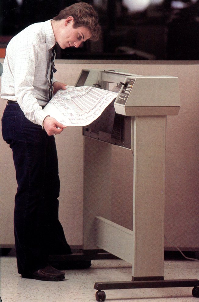
A Breakthrough in the Lab Prototype Phase - From here, development of the 7580A proceeded fairly smoothly throughout the lab prototype phase. By now, the prototypes looked very much like the final product depicted in pictures also available on this site. The elegant industrial design, created by Bart Davis, took full advantage of the unique paper drive mechanism and resulted in a large format plotter that took minimal floorspace, and was easily rolled from place to place on castors.
For readers who would like more detail on individual development team efforts, it can be found in the November 1981 issue of the HP Journal, a copy of which can be downloaded from this website.
As is typical on an R&D project in the development phase, one engineer or another would come forward about once a week with an idea for a new feature that we could include in the final product. Usually I would appreciate their idea but suggest that we put it on the shelf until the "B" model entered development. By then we would have some market feedback that would help us decide which new features would best address unmet customer needs.
One day, though, George Lynch, now the project manager, came into my office with Dave Perach, with one of our mechanical engineers in tow. "Dave has invented a way to cap liquid ink pens and keep them wet and ready to write for up to three weeks." George announced. Dave was famous among our engineering staff as being the guy who never sent a rough sketch to the model shop. Everything he designed was delivered as a flawless India ink drawing. Hating to waste time unclogging and cleaning liquid ink pens, he had launched his own side project to find a way to effectively cap these pens. After trying many different kinds of rubber, he had found one that effectively sealed in the solvents in liquid ink, and kept the pens from drying up. Remembering the plight of the architect in Bath, England, I enthusiastically gave a green light to including this invention in our first release.
Disaster Strikes in Environmental Testing - Once the lab prototype design stabilized and the machine proved capable of creating visually flawless drawings, we moved into production prototype phase and built several machines that were used for various purposes; environmental tests, manual writing, and marketing efforts, to name a few. Work progressed smoothly and according to schedule until disaster struck during environmental testing. A machine had been set up to run continuously overnight in low temperature and humidity conditions. When the technician arrived the next morning, the plotter was sitting there motionless with a completely destroyed D-size drawing wadded up and jammed in the paper-moving mechanism. No cause of this event could be discerned. Once cleared of the jam, the plotter once again worked perfectly. Further tests were done under similar conditions, this time using several prototype plotters in the chamber, and with a technician watching through the window with orders to never take his eyes off of those machines. Sure enough the jam happened again, but the observer claimed that it happened so fast he couldn’t even begin to explain the cause.
For a time we were in a quandary as to how to diagnose this failure mode. Then someone discovered a new, high speed video camera that could run a 30 second tape loop over and over until triggered to stop. We rented one of these instruments, and eventually were able to record the failure in slow motion. The paper moved freely back and forth through the mechanism, until one cycle where the paper extended normally out in front of the plotter and then, in a few milliseconds, swung down and plastered itself tightly to the metal platen and the legs of the plotter. The grit wheels couldn’t pull it loose and simply tore holes in the paper. Then after a short while the paper freed itself, and began to move again. By this time, though, it was no longer properly aligned with the paper path so, as it passed through, it simply wadded up and jammed. Static electricity build-up was the culprit.
A redesign of the platen surface on which the plotting medium moved solved the problem. A textured coating of carbon impregnated Teflon reduced contact area and friction, and it bled away surface charge before it could build up. In addition, the surfaces of the platen skirts hanging down in front and in back of the platter were dimpled outward to ensure that the area of any contact with the plotting medium would be minimal.
The good news is that we found this problem during product verification testing on a few prototype machines, instead of letting the customer discover it for us. Had this been the case, not only would we have created some very dissatisfied customers, we would have had to also retrofit several hundred machines out in the field.
A Spectacular Success at Introduction - In January 1981 San Diego Division introduced not only the 7580A plotter for $15,450, but also a complete line of drafting supplies that HP was prepared to ship. This happy event though, quickly became a good news-bad news story. The good news was that plotter sales took off like a rocket. They were at a rate that was five times greater than our marketing people had forecast. The bad news was that some of our key vendors were not prepared for such volume and struggled to ramp up their capacity to meet the demand. Order delivery times extended out to 4 and 5 months before our supply chain finally caught up with the order rate.
Shortly after the product was introduced, the HP salespeople in Phoenix approached Frank Lloyd Wright’s operation at Taliesin West in Scottsdale. Having never been able to get a foot in the door of this place before, folks there were very receptive to HP this time when promised a demonstration of this new plotter, and a presentation by some of the people who developed it. We removed the legs from the one of our prototype plotters and loaded it into the back of my airplane. Then Bart Davis and I, along with a couple of engineers from the project, flew to the Phoenix Sky Harbor airport where we were met by a cadre of very appreciative HP salespeople. The show at Taliesen West was a great success, and we all enjoyed a guided tour of the place before we departed. The HP sales team insisted on treating us to an early dinner before our departure and, while at table, the sales manager mentioned, "Boy, I sure wish I could get my hands on that prototype for a few days. I could sell a pot full of those things."
I said, "Well, it’s Wednesday and I don’t need this prototype back at work until next Tuesday. Would you be willing to drive it back to San Diego for me, and maybe make a few stops along the way?"
"That’s a deal!" he said.
When he dropped our plotter off in San Diego the next week, he said that literally everyone he showed it to bought at least one. I asked him if, by any chance, he had stopped by that construction site we had visited a couple of years before. "I sure did," he responded, "and that guy we talked to bought one on the spot."
"I guess the 7580A must be worth more than that new pickup truck." I observed.
Epilogue - In the spring of 2013 I was doing booth duty at our Los Altos Rotary Club "Fine Art in the Park" event when an old couple (about my age) walked by. The fellow struck up a conversation which eventually turned to careers from which we each had retired. When he learned that I had spent 20 years in HP R&D he immediately asked, "What products did you do?"
When I mentioned the 7580A, his wife spoke up, "Oh, he has two of those in our basement, and he’s down there running them all day long, every day! He LOVES those things!" He bought them for his company in the late 1980s, and then took them home with him when he retired. Those machines have worked hard and flawlessly for more than 20 years and are still delighting the customer.
To the 7580A development team: My hat’s off to you. You did damn fine work!
| Back | More Images | Product Documentation | Category Accessories |
^ TOP©2004 - 2026 BGImages Australia - All Rights Reserved.
The HP Computer Museum and BGImages Australia are not affiliated with HP Inc. or with Hewlett Packard Enterprise. Hewlett Packard and the HP logo are trademarks of HP Inc and Hewlett Packard Enterprise. This website is intended solely for research and education purposes.