Peripheral Products
 | Pen Plotters Selection: |
| Name: 9125A Flatbed Plotter | |
| Product Number: 9125A | |
| Introduced: 1968 | |
| Division: San Diego | |
| Ad: Click to see, Click to see, Click to see | |
| Original Price: $2475 | |
| Catalog Reference: 1969, P. 131 | |
| Donated by: Dave Brown, New Zealand (photos) |
Description:
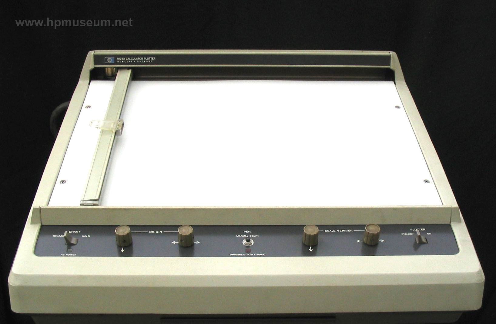
The 9125A was the companion plotter for the 9100 calculator. This single-pen plotter connected to the I/O slot at the back of the 9100. The 9125A had a plotting surface of ten inches by 15 inches and employed electrostatic paper hold down.
The mechanics and industrial design of the 9125A formed the foundation of all HP digital pen plotters until the introduction of the 9872/7221 plotters in 1977.
The 9125A was also a movie star. It made an appearance in the 1971 movie The Andromeda Strain.
The museum is keen to acquire a physical unit of this machine.

Collector's Notes:
Rewinding the Motors in an HP9125A plotter (Tony Duell)
My HP9125A plotter (for the HP9100 series of desktop calculators) had no
motion in the X direction. This was traced to the fact that the drive
motor for that axis had several open-circuit windings on the armature,
and in fact subsequent tests showed that there was one defective winding
in the Y axis motor too. Since these motors are unavailable now, the only
way to get the machine running again was to rewind them. In this article
I will explain the basic procedure for so doing; this information may be
of use for similar plotters such as the HP9862, but I can't be sure of this.
Removing the motors
Obviously, the first job is to remove the motor(s) from the plotter. The X
axis motor is easy to get to, after removing opening the case and
removing the platen, it's just a matter of removing 2 screws on the
bottom of the mechanism chassis and slipping the belt off the motor
pulley. There is a metal mounting plate fixed to the motor with 2 screws,
this is removed next.
The Y axis motor is buried deep inside the plotter mechanism and is much
more difficult to extract. I have found the easiest procedure is to
disconnect the leads from the mechanism at the servo backplane and PSU
module, then to remove the upper case completely (3 screws in the lower
part of the hinge) and then to remove the mechanism from the upper case.
With the X axis motor and drive gear removed, next remove the pen lift
mechanism, the X axis slidewire wiper assembly and the X axis slidewire
itself. Then remove the 7 screws holding the nylon slide rail to the rear
chassis section and the 2 centre screws holding this section to the
chassis plate. Remove the nuts and washers on the end 2 screws (these
also hold 2 of the X axis drive cable pulleys in place, do not remove
these unless you want the `fun' job or restringing it) and remove the rear
chassis section compete (it is linked to the carriage by an electrical
cable). Refit the washers and nuts on the end 2 screws to hold the X axis
pulleys in place. Finally remove the single screw from the motor clamp
(don't drop the nut!) and remove the clamp and motor from the carriage.
In neither case is it necessary to de-solder the wires from the motor
terminals, there is enough slack to allow the motor to be dismantled
while still connected.
Dismantling the motor
The 2 motors differ only in the drive and mounting arrangements. The X
axis motor has a pulley pressed onto the armature spindle (to drive a
mylar belt) and is held to its mounting plate with 2 screws. The Y axis
motor has pinion gear teeth cut into the armature spindle and is mounted
by a plastic clamp which fits into a groove in the front housing. The
dismantling and repair procedures are essentially the same for both motors.
The motors have a 7 pole armature and a permanent magnet field. It is
important to fit a `keeper' to the field magnet when the armature is
removed to prevent demagnetization. A suitable keeper is a piece of soft
iron or mild steel (it must be magnetic!) rod 1/2" in diameter. If you
have the facilities, you can make a nicer keeper from a larger diameter
rod with a little flange at one end, a 1/2" section about 1" long to fit
into the field magnet and a chamfered end to easily slip into the magnet.
It won't do the job any better though.
Having made the keeper, it's time to dismantle the motor. Unhook the ends
of the torsion-type brush springs, rotate the springs in the end housing so
that they come free, and slide them out. Using a pair of tweezers, pull
the brush pigtails to lift the brushes off the commutator. Mark the brush
end cap and the field magnet yoke so you can get them back in the same
orientation (footnote: it is not a big problem if you get this wrong, the
motor will simply run backwards and the servo system will not lock. No
damage is done, you simply have to turn the field magnet round or reverse
the connections to the brushes). Unscrew the 2 long throughbolts on the
brush end housing and slide them out. The motor components are now all
free, but how they come apart depends on which motor it is.
In the case of the X-axis motor, the armature cannot come free from the
drive end housing due to the pulley on the spindle. So the brush end
housing comes off first, followed by a small intermediate flange. Then
slide off the filed magnet and insert the keeper. The pulley needs to be
removed next, preferably using a puller tool. Then remove the drive end
housing, any shims from the outside of the ball race, and the ball race
itself.
In the Y-axis motor, the drive end housing normally slides off first,
followed by any bearing shims and the ball race, Then remove the field
magnet and fit the keeper. Take off the intermediate flange and pull the
armature out of the brush end housing.
Put the other parts of the motor aside and examine the armature. A good
armature will have a resistance of about 2ohm to 3ohm between
adjacent commutator segments, and the resistance will be the same for all
7 adjacent pairs. This is quite easy to check. If you find a much higher
resistance or an open circuit, then at least one winding has failed.
Rewinding the armature
If a winding has failed, then it's generally necessary to rewind all 7
coils, which sounds worse than it actually is. It took me about half an
hour to do completely rewind each armature.
The first stage in the rewind is, of course, to remove the old wire.
Desolder the ends from the commutator segments. Then soak the armature in
methylated spirits to dissolve the shellac holding the windings in place.
When this has softened, pull out the covering strips from each armature
slot (you do not need to refit these after the rewind) and start
unwinding the wire. If you find you can't unwind one turn at a time, cut
through the windings at the drive end of the armature, and pull the
bundles of wire out.
There are 4 parameters needed to correctly rewind the armature. The
diameter of the wire, the number of turns on each coil, how many slots
the coils span, and how the coils are connected to the commutator. In
this case, each coil has 40 turns of 0.006" (SWG 38) wire, there are 2
slots between the slots occupied by the turns of any one coil, the ends
of a coil go to adjacent commutator segments with the 'end' of the
winding connected to the segment immediately above its slot.
So let’s start winding. Hold the armature with the commutator end away from
you and solder one end of the reel of wire to an arbitrary commutator
segment. Take the wire down the slot 2 slots to the left (as you look at
the armature) of that segment, to the right at the drive end of the
armature, skipping 2 slots and up the next slot. This will bring it up
immediately under the next commutator segment to the right. That's one
turn of the coil. Turn the wire to the left at the commutator end, down,
to the right and up the same slots for the second turn. Repeat until 40
turns have been wound. Then take a loop of the wire, twist it, and solder
to the next segment to the right (of the one you started on). Repeat this
procedure until all 7 coils have been wound, the last end will be coming
up the slot immediately below the segment where the start of the wire was
soldered. Connect it to that segment (leaving the `start' wire in place).
Let me explain that in a different way. Arbitrarily number the armature
slots from 1 to 7 going anticlockwise looking at the commuatotor end of
the armature. Give the segments the same number as the slot they are
immediately over. Start by soldering the wire to segment 1. Take it to
the left at the commutator end, down slot 6, across the drive end,
skipping slots 7 and 1, and up slot 2. Wind on 40 turns like that, then
make a loop in the wire, twist it together, and solder to segment 2. Wind
the next coil down slot 7 and up slot 3 for another 40 turns, make a
loop, twist, and solder to segment 3. Repeat until all 7 coils are wound.
Check the resistance between adjacent segments as before. If one segment
seems to be open circuit, check the soldering to that segment. Now trim
off the excess wire and file off and excess solder (the clearances in the
brush end housing are tight), and check again.
Reassemble the motor, lining up the marks you made earlier. Disconnect
the motor wires form the PSU module (if you have not already done so to
remove the complete mechanism from the plotter) and test the motor using
a bench power supply. It should run smoothing from about 2V to 14V and
draw about 150mA. If you have a stroboscope, I can provide the speed
against voltage data for the rewound motors in my plotter, should you
wish to check yours (footnote: If you don't have a stroboscope and wish do
do this test, I can provide a schematic of a simple strobe using white
LEDs as the light source).
If the motor runs properly, reassemble the plotter, and hopefully it will
work correctly once more.
A couple of hints for reassembling the slidewires
Reassembling the slidewire wipers without damage can be difficult, so here
are 2 hints, one for each axis. The part number references refer to figure
4-1 in the HP9125B service manual.
When reinserting the pen carriage (7) to the pen arm (27), use a feeler
blade (about 0.015") as a ramp to guide the wipers onto the slidewire
assembly. Otherwise the limit switch wipers will get bent.
Refitting the X axis wiper assembly (39) is tricky. It is considerably
easier if the fixing screw (34) is replaced by one with an allen cap head
which can be guided into place on the end of an allen driver. Fit the
wiper assembly and hold it against the bracket (38) using a suitable rod
such as another allen driver. Then fit the screw and tighten. You may
have to elongate the mounting hole in the pen solenoid clip (35) with a
file after fitting the allen cap head screw but this is not a major problem.
| Back | More Images | Product Documentation | Category Accessories |
^ TOP©2004 - 2026 BGImages Australia - All Rights Reserved.
The HP Computer Museum and BGImages Australia are not affiliated with HP Inc. or with Hewlett Packard Enterprise. Hewlett Packard and the HP logo are trademarks of HP Inc and Hewlett Packard Enterprise. This website is intended solely for research and education purposes.